High-Precision Personnel Magnetic Positioning System in a Coal Preparation Plant

No base stations · Immune to obstruction and interference · Positioning accuracy better than 1m · Deployed at coal preparation plants of major state-owned coal enterprises

<1m
Positioning accuracy
111
Test points
90%+
Points with error <1m
Zero
base stations to build
01 Project Background Pain-Point Analysis

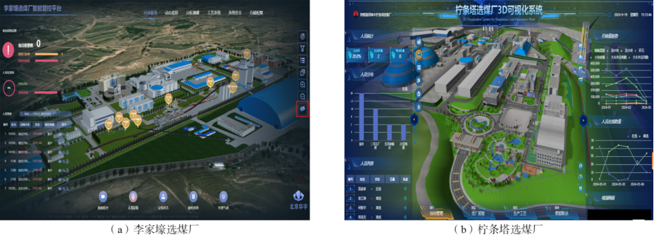
Coal preparation plants are a critical link in coal production and processing, and a high-precision personnel positioning system is an essential component of smart coal preparation plant construction. Management needs real-time visibility of personnel distribution across the plant and of movement trajectories.

Conventional UWB positioning faces three major pain points in the complex environment of a coal preparation plant:

To solve these problems, drawing on research into geomagnetic positioning for aircraft, this solution fuses magnetic positioning technology with an IMU — and it has been successfully deployed at coal preparation plants of major state-owned coal enterprises.

Article source: Intelligent Mine magazine, Issue 12, 2025 · Zhang Xuke, Liu Keyan · Zhongxuan Zhikong (Tianjin) Technology Co., Ltd.
02 Technical Principle Magnetic Positioning

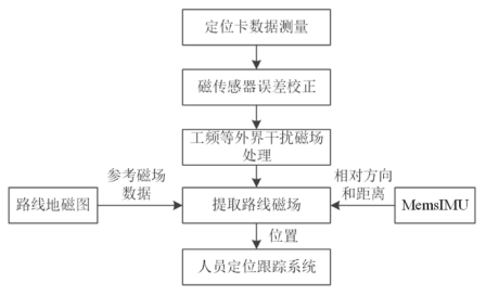
The magnetic field data of the working area is first measured to build a magnetic reference map. Personnel wear positioning terminals whose magnetometers sample the magnetic field along their walking routes, forming a real-time map; the measured data is then matched against the magnetic reference map database to determine each person's position.

Working principle of magnetic positioning inside a coal preparation plant
Fig. 2 Working principle of magnetic positioning inside a coal preparation plant

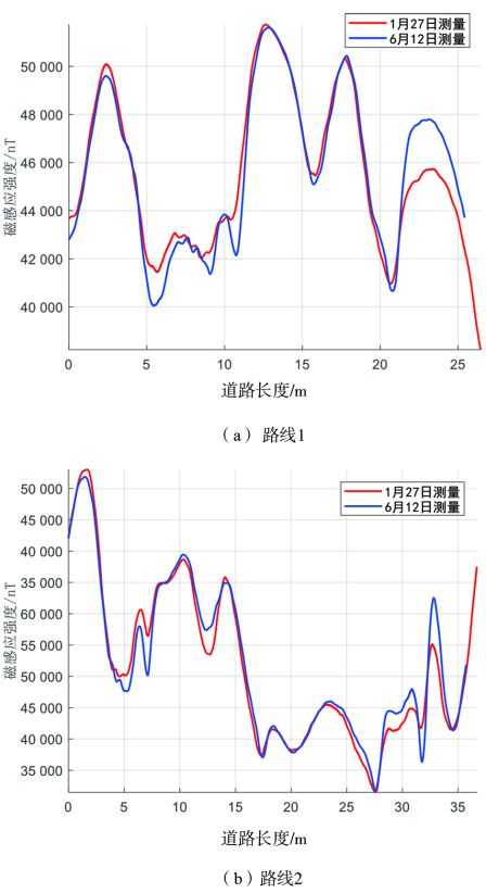
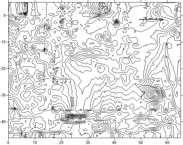
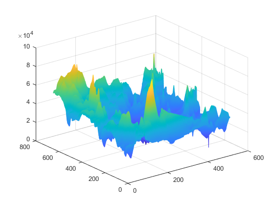
Experiments show that the magnetic field differs significantly between routes and that the field characteristics are stable over time (a distribution unchanged over months), so the magnetic map does not need frequent updates once built.

03 System Composition Equipment Architecture

System Architecture

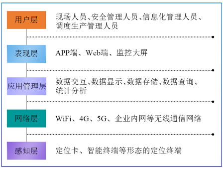
The system comprises the perception layer (positioning terminals), the network layer (WiFi/4G/5G), the application management layer (positioning engine), the presentation layer and the user layer.

Composition of the personnel magnetic precision positioning system
Fig. 4 Composition of the personnel magnetic precision positioning system

📱 Positioning Terminal

Includes personnel positioning badges and smart terminals, with a built-in magnetometer continuously sampling the magnetic field and sending data to the positioning engine over WiFi/4G.

An SOS button triggers an alarm: the buzzer sounds in an SOS pattern while the red LED on the left flashes in sync. The terminal also supports automatic detection and alarm of abnormal behaviors such as falls, immobility and falls from height.

Personnel magnetic precision positioning badge
Fig. 6 Personnel magnetic precision positioning badge

⚙️ Positioning Engine

The positioning engine is the core of the magnetic positioning system. Data processing workflow:

  1. Error-correct the raw magnetometer data
  2. Filter out interference fields such as power-frequency noise
  3. Use the IMU to provide relative direction and distance between points
  4. Match the route's magnetic field features against the reference magnetic map
  5. Output position coordinates to the business system
Magnetic positioning data processing workflow
Fig. 7 Magnetic positioning data processing workflow
04 Building the Magnetic Reference Map Field Mapping

Magnetic field data is collected with a professional LiDAR-based magnetic surveying device. The device consists of a non-magnetic cart, a LiDAR unit, magnetometers, an industrial control board and more — pushing the cart along a route captures position and magnetic field data simultaneously.

Magnetic map surveying device
Fig. 8 Magnetic map surveying device
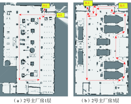
Magnetic map collection route
Fig. 9 Magnetic map collection route (LiDAR mapping)

The LiDAR measures the indoor map and position information via SLAM, with positioning accuracy better than 0.1m. Bilinear interpolation grids the raw magnetic field data uniformly to generate the magnetic reference map. The data includes latitude, longitude and magnetic induction strength (Lat, Lon, B) in a geographic coordinate system.

05 Accuracy Validation Field Testing

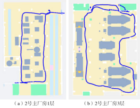
One magnetic positioning system was deployed at the coal preparation plant, and positioning accuracy on floors 1–6 of the No. 2 main plant building was tested with the following procedure:

  1. Select key points along the test routes for positioning tests — 111 test points in total across floors 1–6. The key points on floors 1 and 3 are marked as shown in Fig. 13, and the actual coordinates of all test points are recorded.
  2. Testers wear the positioning terminals and walk along the predefined trajectories.
  3. Afterwards the positioning trajectories are extracted, the coordinates near each test point are compared with the actual coordinates, and the positioning error is computed.
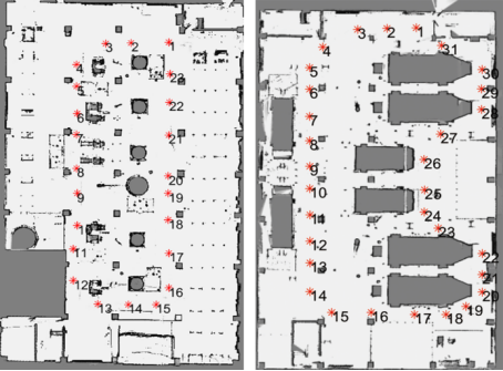
Magnetic positioning accuracy test routes
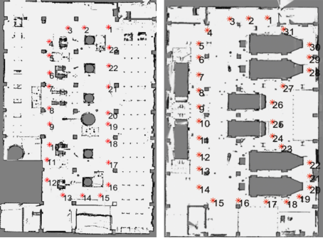
Fig. 12 Magnetic positioning accuracy test routes
Key test points
Fig. 13 Key test points (floors 1 and 3)

The positioning trajectory is shown in Fig. 14; results show the computed positions match the actual walking route. A real-scene vs. 3D comparison of reference point No. 44 is shown in Fig. 15.
Positioning trajectory
Fig. 14 Positioning trajectory
Real-scene and 3D comparison of reference point No. 44
Fig. 15 Real-scene and 3D comparison of reference point No. 44

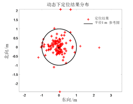
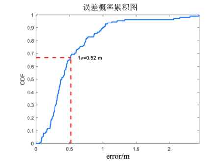
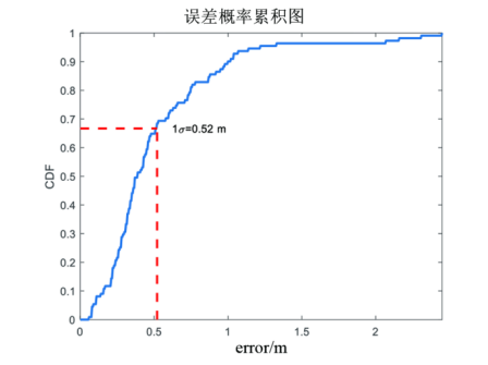
The positioning errors of the 111 selected test points are shown in Fig. 16, and the cumulative error probability distribution in Fig. 17 — over 90% of points have errors below 1m.
Positioning error results
Fig. 16 Positioning error results
Cumulative error probability distribution
Fig. 17 Cumulative error probability distribution
MetricValue
Total test points111 (floors 1–6)
Positioning error of 90%+ of points< 1m
Mean positioning error (1σ)Meets precision positioning requirements
Floors covered6-story main plant building
06 Results in Operation Real-World Deployment

📊 Real-Time Personnel Distribution

View real-time headcounts per zone, positions and entry/exit times on a 3D map, with full display on linked monitoring screens.

Real-time personnel distribution view
Fig. 18 Real-time personnel distribution view

🚨 Abnormal-Event Alarms

One-touch SOS, fall detection, and boundary-crossing / wrong-zone / immobility / crowding alarms to speed up emergency response.

🔍 Trajectory Replay

Visualize live and historical walking trajectories, with entry/exit records available on demand.

🏭 Base-Station-Free Deployment

No anchor installation, strong interference immunity, and high positioning accuracy in complex industrial environments.

07 Conclusion
The personnel positioning system based on magnetic positioning technology meets the high-precision positioning needs of coal preparation plants. It requires no base-station installation, is simple to maintain, resists obstruction and metal interference, and suits personnel positioning management in coal preparation plants with complex multi-level platforms. Field deployments have verified positioning accuracy better than 1m, satisfying precision requirements. The approach can also be extended to other industrial indoor positioning scenarios.
← Back to the MagNav PDR product page

Reference: Zhang Xuke, Liu Keyan. Development and application of a high-precision personnel magnetic positioning system for coal preparation plants [J]. Intelligent Mine, 2025, 6(12): 36-42.

Authors' affiliation: Zhongxuan Zhikong (Tianjin) Technology Co., Ltd.